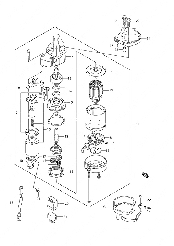
Fig. 19 - Starting Motor для Suzuki DF 25 V-Twin - 2006 года выпуска

-
№АртикулНазвание
-
131100-95J01-000 Starter Motor AssemblyStarter Motor Assembly
-
231131-94J00-000 • Plus Brush Set• Plus Brush Set
-
331135-90J00-000 • Spring• Spring
-
431151-94J01-000 • Gear Case• Gear Case
-
531152-90J00-000 • Center Plate (NLA)• Center Plate (NLA)
-
631153-90J00-000 • Planet Gear Bracket (NLA)• Planet Gear Bracket (NLA)
-
731171-96J00-000 • Dust Cover Kit• Dust Cover Kit
-
831173-94J01-000 • Brush Holder• Brush Holder
-
931191-96J00-000 • Shift Lever (NLA)• Shift Lever (NLA)
-
1031220-94J00-000 • Magnet Switch• Magnet Switch
-
1131310-90J00-000 • Armature• Armature
-
1231320-94J00-000 • Pinion Assembly (NLA)• Pinion Assembly (NLA)
-
1331341-94J00-000 • Pinion Shaft (NLA)• Pinion Shaft (NLA)
-
1431343-90J00-000 • Internal Gear (NLA)• Internal Gear (NLA)
-
1531344-90J00-000 • Planetary Gear (NLA)• Planetary Gear (NLA)
-
1631360-93J01-000 • Washer Set• Washer Set
-
1731913-93J00-000 • Terminal• Terminal
-
1831914-93J00-000 • Terminal Cap• Terminal Cap
-
1931912-95J00-000 Starting Motor Band (NLA)Starting Motor Band (NLA)
-
2031918-95J00-000 Starter Damper (NLA)Starter Damper (NLA)
-
2108316-10087-000 NutNut
-
2201550-08207-000 Bolt (8x20)Bolt (8x20)
-
2301550-08257-000 BoltBolt
-
2431911-95J00-000 Starting Motor Bracket (NLA)Starting Motor Bracket (NLA)
-
2501550-08307-000 BoltBolt
-
2604211-11129-000 Dowel Pin (11x12)Dowel Pin (11x12)
-
2704221-06129-000 Pin (6x12)Pin (6x12)
-
2836645-94J00-000 Wire Lead (NLA)Wire Lead (NLA)
-
2938860-76F01-000 RelayRelay
-
3038915-90J00-000 Relay HolderRelay Holder
Все узлы модели:
-
Fig. 1 - Cylinder Head
S/N 02502F-680001 to 02502F-68XXXX -
Fig. 2 - Cylinder Block
S/N 02502F-680001 to 02502F-68XXXX -
Fig. 3 - Crankshaft
S/N 02502F-680001 to 02502F-68XXXX -
Fig. 4 - Camshaft
S/N 02502F-680001 to 02502F-68XXXX -
Fig. 7 - Magneto Cover/Recoil Starter/Silencer
S/N 02502F-680001 to 02502F-68XXXX -
Fig. 8 - Fuel Pump
S/N 02502F-680001 to 02502F-68XXXX -
Fig. 9 - Water Pump
S/N 02502F-680001 to 02502F-68XXXX -
Fig. 10 - Thermostat
S/N 02502F-680001 to 02502F-68XXXX -
Fig. 11 - Throttle Control Non-Remote Control
S/N 02502F-680001 to 02502F-68XXXX -
Fig. 12 - Throttle Control Remote Control
S/N 02502F-680001 to 02502F-68XXXX -
Fig. 13 - Oil Pump
S/N 02502F-680001 to 02502F-68XXXX -
Fig. 14 - Oil Pan
S/N 02502F-680001 to 02502F-68XXXX -
Fig. 16 - Clutch Shaft Remote Control
S/N 02502F-680001 to 02502F-68XXXX -
Fig. 17 - Clutch Rod
S/N 02502F-680001 to 02502F-68XXXX -
Fig. 18 - Drive Shaft
S/N 02502F-680001 to 02502F-68XXXX -
Fig. 20 - Magneto
S/N 02502F-680001 to 02502F-68XXXX -
Fig. 21 - Rectifier/Ignition Coil
S/N 02502F-680001 to 02502F-68XXXX -
Fig. 22 - Sensor/Switch
S/N 02502F-680001 to 02502F-68XXXX -
Fig. 23 - Harness
S/N 02502F-680001 to 02502F-68XXXX -
Fig. 24 - Clamp Bracket
S/N 02502F-680001 to 02502F-68XXXX -
Fig. 25 - Swivel Bracket
S/N 02502F-680001 to 02502F-68XXXX -
Fig. 26 - Drive Shaft Housing
S/N 02502F-680001 to 02502F-68XXXX -
Fig. 28 - Side Cover
S/N 02502F-680001 to 02502F-68XXXX -
Fig. 29 - Engine Cover
S/N 02502F-680001 to 02502F-68XXXX -
Fig. 30 - Tiller Handle
S/N 02502F-680001 to 02502F-68XXXX -
Fig. 31 - Fuel Tank
S/N 02502F-680001 to 02502F-68XXXX -
Fig. 32 - Remocon Cable Remote Control
S/N 02502F-680001 to 02502F-68XXXX -
Fig. 34 - Remote Control Box
S/N 02502F-680001 to 02502F-68XXXX -
Fig. 36 - Opt: Switch
S/N 02502F-680001 to 02502F-68XXXX -
Fig. 37 - Opt: Top Mount Single (1)
S/N 02502F-680001 to 02502F-68XXXX -
Fig. 38 - Opt: Top Mount Single (2)
S/N 02502F-680001 to 02502F-68XXXX -
Fig. 39 - Opt: Concealed Remocon (1)
S/N 02502F-680001 to 02502F-68XXXX -
Fig. 40 - Opt: Concealed Remocon (2)
S/N 02502F-680001 to 02502F-68XXXX -
Fig. 41 - Opt: Remocon Attachment
S/N 02502F-680001 to 02502F-68XXXX -
Fig. 43 - Opt: Harness
S/N 02502F-680001 to 02502F-68XXXX -
Fig. 44 - Opt: Starting Motor
S/N 02502F-680001 to 02502F-68XXXX -
Fig. 45 - Opt: Remocon Parts Set
S/N 02502F-680001 to 02502F-68XXXX -
Fig. 46 - Opt: Gasket Set
S/N 02502F-680001 to 02502F-68XXXX -
Fig. 15 - Clutch Shaft Non-Remote Control
S/N 02502F-680001 to 02502F-68XXXX - • Fig. 19 - Starting Motor
S/N 02502F-680001 to 02502F-68XXXX -
Fig. 27 - Gear Case
S/N 02502F-680001 to 02502F-68XXXX -
Fig. 33 - Drag Link Remote Control
S/N 02502F-680001 to 02502F-68XXXX -
Fig. 35 - Opt: Meter
S/N 02502F-680001 to 02502F-68XXXX -
Fig. 42 - Opt: Electrical
S/N 02502F-680001 to 02502F-68XXXX -
Fig. 5 - Intake Manifold
S/N 02502F-680001 to 02502F-68XXXX -
Fig. 6 - Carburetor
S/N 02502F-680001 to 02502F-68XXXX