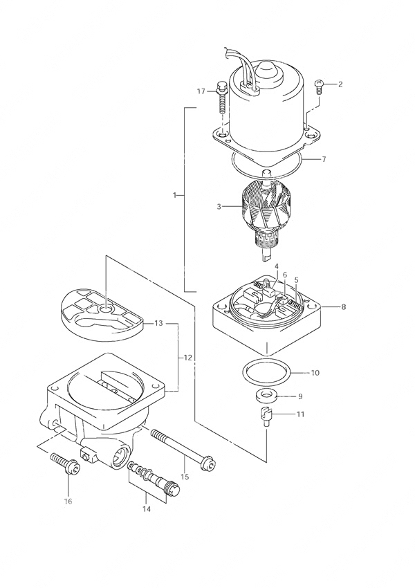
Fig. 39 - Power Unit для Suzuki DF 60 - 2000 года выпуска
-
№АртикулНазвание
-
138100-99E01-0EP PTT Motor AssemblyPTT Motor Assembly
-
231111-94900-000 • Yoke Screw• Yoke Screw
-
331311-94900-000 • Armature (NLA)• Armature (NLA)
-
431133-94910-000 • Brush• Brush
-
531135-94900-000 • Spring• Spring
-
631136-94900-000 • Breaker (NLA)• Breaker (NLA)
-
731123-87D60-000 • O-Ring• O-Ring
-
831173-94920-000 • Brush Holder Assembly• Brush Holder Assembly
-
933799-97E00-000 Oil SealOil Seal
-
1048585-95E00-000 O-RingO-Ring
-
1148583-95E00-000 Drive JointDrive Joint
-
1248502-94901-000 PTT Pump AssemblyPTT Pump Assembly
-
1348582-95E01-000 • Filter• Filter
-
1448864-94911-000 • Manual Valve Set• Manual Valve Set
-
1548862-95E00-000 BoltBolt
-
1648862-95E10-000 BoltBolt
-
1731281-95E00-000 Through BoltThrough Bolt
Все узлы модели:
-
Fig. 8 - Inlet Manifold
S/N 06001F-030001 to 06001F-03XXXX -
Fig. 12 - Silencer
S/N 06001F-030001 to 06001F-03XXXX -
Fig. 13 - Exhaust Manifold
S/N 06001F-030001 to 06001F-03XXXX -
Fig. 20 - Water Pump
S/N 06001F-030001 to 06001F-03XXXX -
Fig. 33 - Harness
S/N 06001F-030001 to 06001F-03XXXX -
Fig. 41 - Engine Holder
S/N 06001F-030001 to 06001F-03XXXX -
Fig. 45 - Transmission
S/N 06001F-030001 to 06001F-03XXXX -
Fig. 47 - Side Cover
S/N 06001F-030001 to 06001F-03XXXX -
Fig. 48 - Engine Cover
S/N 06001F-030001 to 06001F-03XXXX -
Fig. 49 - Tiller Handle
S/N 06001F-030001 to 06001F-03XXXX -
Fig. 50 - Fuel Hose
S/N 06001F-030001 to 06001F-03XXXX -
Fig. 51 - Drag Link
S/N 06001F-030001 to 06001F-03XXXX -
Fig. 52 - Opt: Remote Control
S/N 06001F-030001 to 06001F-03XXXX -
Fig. 59 - Opt: Meter
S/N 06001F-030001 to 06001F-03XXXX -
Fig. 62 - Opt: Trim Sender
S/N 06001F-030001 to 06001F-03XXXX -
Fig. 63 - Opt: Harness
S/N 06001F-030001 to 06001F-03XXXX -
Fig. 65 - Opt: Switch
S/N 06001F-030001 to 06001F-03XXXX -
Fig. 2 - Cylinder Block
S/N 06001F-030001 to 06001F-03XXXX -
Fig. 3 - Under Oil Seal Housing
S/N 06001F-030001 to 06001F-03XXXX -
Fig. 4 - Crankshaft
S/N 06001F-030001 to 06001F-03XXXX -
Fig. 5 - Timing Belt
S/N 06001F-030001 to 06001F-03XXXX -
Fig. 15 - Fuel Vapor Separator
S/N 06001F-030001 to 06001F-03XXXX -
Fig. 18 - Fuel Injector
S/N 06001F-030001 to 06001F-03XXXX -
Fig. 19 - Fuel Pump
S/N 06001F-030001 to 06001F-03XXXX -
Fig. 21 - Thermostat
S/N 06001F-030001 to 06001F-03XXXX -
Fig. 22 - Throttle Body
S/N 06001F-030001 to 06001F-03XXXX -
Fig. 23 - Oil Pump
S/N 06001F-030001 to 06001F-03XXXX -
Fig. 24 - Oil Pan
S/N 06001F-030001 to 06001F-03XXXX -
Fig. 25 - Clutch Shaft
S/N 06001F-030001 to 06001F-03XXXX -
Fig. 26 - Shift Rod
S/N 06001F-030001 to 06001F-03XXXX -
Fig. 27 - Starting Motor
S/N 06001F-030001 to 06001F-03XXXX -
Fig. 29 - Magneto
S/N 06001F-030001 to 06001F-03XXXX -
Fig. 31 - Ignition Coil
S/N 06001F-030001 to 06001F-03XXXX -
Fig. 32 - Sensor
S/N 06001F-030001 to 06001F-03XXXX -
Fig. 34 - Engine Control Unit
S/N 06001F-030001 to 06001F-03XXXX -
Fig. 35 - Clamp Bracket
S/N 06001F-030001 to 06001F-03XXXX -
Fig. 36 - Swivel Bracket
S/N 06001F-030001 to 06001F-03XXXX -
Fig. 37 - Trim Cylinder
S/N 06001F-030001 to 06001F-03XXXX - • Fig. 39 - Power Unit
S/N 06001F-030001 to 06001F-03XXXX -
Fig. 42 - Driveshaft Housing
S/N 06001F-030001 to 06001F-03XXXX -
Fig. 43 - Gear Case
S/N 06001F-030001 to 06001F-03XXXX -
Fig. 67 - Opt: Tiller Handle
S/N 06001F-030001 to 06001F-03XXXX -
Fig. 1 - Cylinder Head
S/N 06001F-030001 to 06001F-03XXXX -
Fig. 6 - Camshaft
S/N 06001F-030001 to 06001F-03XXXX -
Fig. 68 - Optional
S/N 06001F-030001 to 06001F-03XXXX